Files
Scanning the repository...
Last update 7 years 9 months
by cadlab-io[bot]
| Files | |
|---|---|
| .gitignore | |
| DS2482 Breakout.brd | |
| DS2482 Breakout.pro | |
| DS2482 Breakout.sch | |
| README.md |
README.mdView this project on CADLAB.io.

DS2482 Breakout

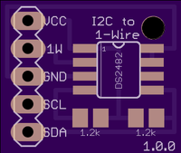
Eagle layout for a breakout board for the Maxim DS2482 I2C to 1-wire chip


This is a work in progress! I just sent the boards off to OSH Park for etching, so I haven't confirmed it actually works yet.

Components
- 1 x Maxim DS2482 Single-Channel 1-Wire Master
- 2 x 1.2k SMD resistors (Package: M0805 )
Pin out of connector (looking component side up, connector on the left)
- Vcc - Nominally 5V. You can use 3.3V but the pull up resistors probably nned to be changed
- 1-wire - the 1-wire network wire
- Ground.
- The SCL pin on the I2C interface
- The SDA pin on the I2C interface
Ardiuno Sample code
Coming soon...
References
https://www.maximintegrated.com/en/products/interface/controllers-expand...


