


Files
README.mdView this project on CADLAB.io.
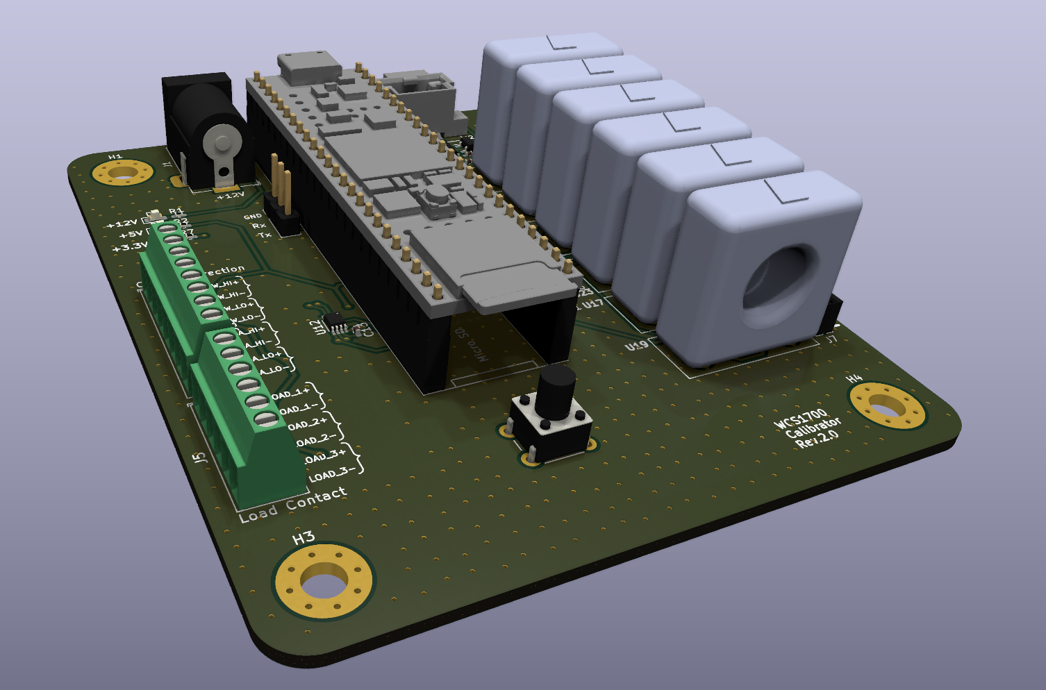
WCS1700-Calibrator
A board designed to aid in calibrating six Winson WCS1700 hall effect sensors at the same time as well as the software needed to drive it.
Requirements
- +12V power supply rated for at least 1A with barrel jack connection (+8V will work in a pinch)
- An adjustable current source capable of up to 60A output with a conductor small enough to fit the aperture of a WCS1700
- A micro-USB cable with data capability
- A Teensy 4.1 microcontroller and completion of the necessary first use steps
- For best results, VSCode with the Platformio plugin installed
Hardware
Schematic and BOM can both be found in the
/hardware/section of this repository. Expanded description of hardware functionality coming soon.Software
All software can be found in the
/software/section of this repository. Expanded description of software functionality coming soon. In addition, software updates to expand contactor control functionality and independent current volume is on the way, but the software necessary to simply monitor and report the WCS1700 hall effect sensor outputs is ready and implemented.Procedure
- Slot one WCS hall effect sensor into each of the six ports on the right. This will feed them a +5V reference and allow their output voltages to be tracked via a nearby ADC
- Inspect your Teensy 4.1. If the trace separating VIN and VUSB is cut, you should solder JP3 on the PCB. If not, you should ensure that either the aforementioned Teensy trace is intact or that the pads spanned by said trace are soldered together. Do not do both or you risk damaging your Teensy or the board
- Ensure that JP1 and JP2 are not soldered simultaneously. It is okay to solder one or the other (or neither) but do not do both or you risk damaging your board
- Seat your Teensy 4.1 in the pin sockets and connect it to your computer via USB
- Route your current source conductor through the hall effect sensor apertures and attach a load
- Apply power to the PCB
- Monitor the serial output from the Teensy 4.1
- Adjust your current source as desired
Assembly Guide
An assembly guide for this board can be found in this repository at
/hardware/bom/To-Do
The hardware of this project has advanced to support contactor control via relay connections. Four of these contactors form a would-be H-bridge to control load current flow direction while the remaining three allow current flow across individual load resistors to increase or decrease current volume. The hardware has also advanced to support independent current monitoring via a Tamura L01Z series hall effect sensor. The software to drive these features is not yet in place. The following is a list of development items not yet complete:
- [x] Rearrange FET position and routing to make it a superior low-side switch
- [ ] Add harness documentation
- [ ] Write code to support autocalibration of ADC
U4 - [ ] Write code to support monitoring of Tamura L01Z Hall Effect sensor via ADC 'U5'
- [ ] Write logic to support contactor control during current monitoring after button push
- [ ] Write code to support logging recorded calibration values to an SD card
- [ ] Update instructions to allow for use of additional Tamura hall effect sensor as well as contactor control