


Files
| Files | |
|---|---|
| board | |
| images | |
| src | |
| .gitignore | |
| LICENSE.txt | |
| README.md |
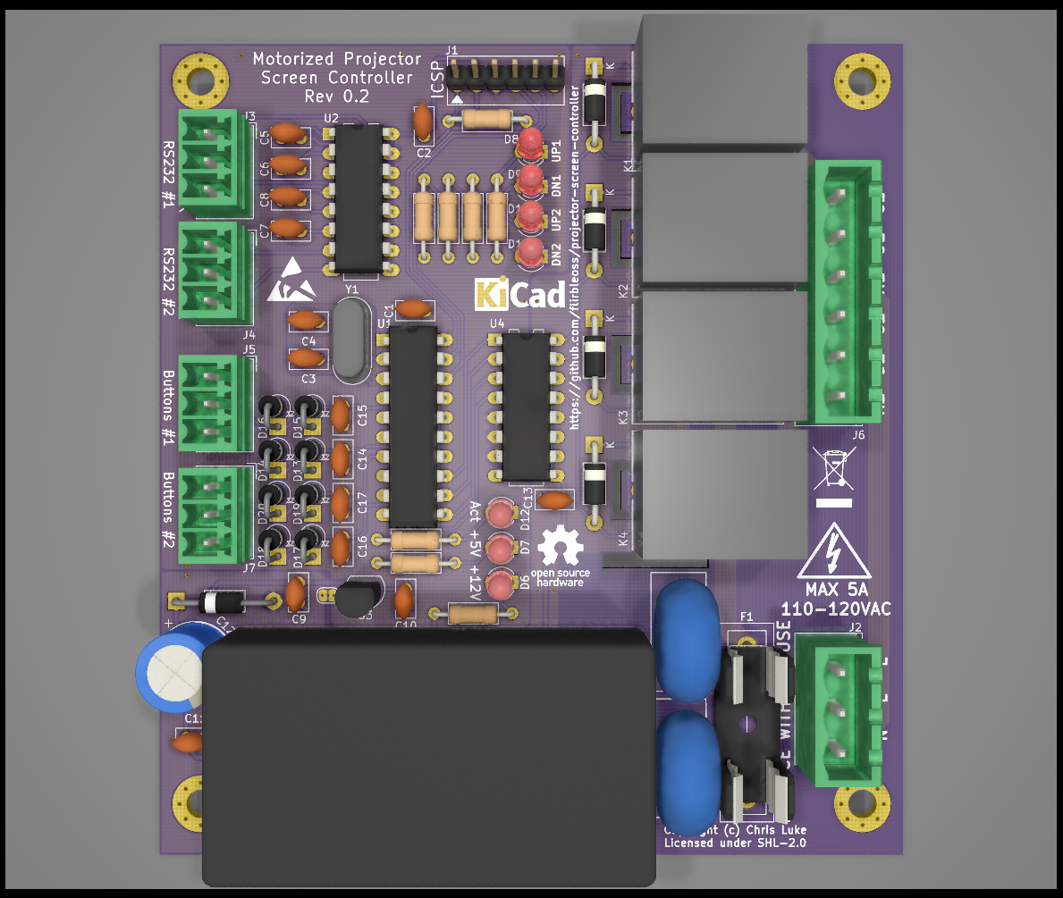
README.mdProjector Screen Controller

Simple controller for basic motorized projector screens. An almost-drop-in
replacement for the Da-Lite SCB-100.

Status: Work in progress

Background

Tired of the commercial screen controller letting out its magic smoke every
couple of years and not content with the $400 replacement cost, I decided to
make my own almost-drop-in replacement with more emphasis on electronic
protection than the commercial variant seems to have.

In my analysis of both SCB-100s that failed, it appeared a transient condition
upset the MAX232 driver such that it causes a dead-short between the 5v and 0v
rails. The charge pump capacitors of the MAX232 chip are adjacent to the
ULN2003 relay driver and the 12V decoupling capacitor. The design relies on
the diodes in the ULN2003 for back-EMF suppression, which I speculate may not
be adequate for the off-brand relays in use in both of my SCB-100s (an online
search reveals other specimens have relays from a more reputable brand,
however.) Finally, the switching power supply module is soldered to the back
of the logic board. While there is a plastic divider between the boards, there
is only a few milimeters of space and line voltage spikes may well cause
interference; additionally there are several places where line voltage and
signal voltage traces come closer than I would be comfortable with.

It is my conclusion therefore that the failures are likely caused by
insufficient physical isolation and insufficient transient back-EMF
suppression.

Design objectives
- Same form-factor for the board, so it can use the same metal case in-situ.
- Connections in roughly the same locations, with the same pin ordering.
- Use removable Phoenix connectors with screw terminals throughout.
- Improved electronic protection;
- Better flyback suppression from the relays.
- DC power protection in case the power supply fails.
- Physical board isolation (with board cut-outs) between line voltages and the 5V/12V sections, especially around the relays.
- Better isolation between 12V and 5V sections, to avoid relay noise issues.
- Modern high-efficiency switching power supply with plenty of protection features.
- More indicator LEDs to show what is going on.
- Backward-compatible RS232 protocol, but enhancements to allow customizing, for example, the motor run time.
- Open-source design.
Implementation
Preview
TODO
Actions
- Verify spacing of connectors to edge wrt the case lid.
- Power-side connectors probably need to move to the left by ~1mm
- Write the firmware.
- The TVS diode was larger than anticipated, make room.
- The xtal load caps are larger (with wider pin spacing) than anticipated; find smaller.