


Files
-
addon board / C64Saver2-addon.kicad_pcb
-
addon board / C64Saver2-addon.sch
-
addon board / rescue-backup / C64Saver2-addon-2019-05-19-18-52-40.sch
-
C64 Saver 2 / C64Saver2.kicad_pcb
-
C64 Saver 2 / C64Saver2.sch
-
old-saver / 1.0 / c64saver.brd
-
old-saver / 1.0 / c64saver.sch
-
old-saver / 1.1-1.3 / c64saver_1.1.brd
-
old-saver / 1.1-1.3 / c64saver_1.1.sch
-
old-saver / 1.1-1.3 / c64saver_1.2.brd
-
old-saver / 1.1-1.3 / c64saver_1.3.brd
-
old-saver / 1.1-1.3 / c64saver_1.3.sch
| Files | |
|---|---|
| C64 Saver 2 | |
| addon board | |
| kicad-libraries | |
| old-saver | |
| .gitattributes | |
| .gitignore | |
| LICENSE.txt | |
| README.md |
README.mdC64 Saver v1 and v2 - Overvoltage protection for the C64 and its power brick.
Designed by BWACK 2018 CERN OPEN HARDWARE LICENSE v1.2 http://www.ohwr.org/
The KiCad and other design files are available on GitHub: https://github.com/bwack/
All text above must be included in any redistribution
Bwack's C64 saver designs.
The C64 Saver 2 is an open-source project intended to make overvoltage protection available and easy to make for anyone interested in using the old Commodore power brick together with the C64. The power brick is 20-30 years old and it is known for failure with overvoltage. This is caused sometimes because of broken solder joints on the regulator or the regulator itself failing.
What has changed in v2 ?
- The design is modular.
- Spike protection. Handles hotswapping and switch bouncing better.
- It is much much easier and faster to make. Most people can make it, and not just me who don't want to do the v1 anymore anyway. Insane how much time that took god damnit.
The C64 Saver 2 (base board)
The base board is all you need for overvoltage protection. Through hole parts except for the mosfet, but it is large and easy to solder. The board shape fits the Hammond 1551g project case. * Note: For the C64 Saver 2 work standalone (without addon board), J2 needs to be bridged and so does J4. This is done by a solder blob or a link where you see the power path is "broken" in the middle of the pinheaders. This is intended to allow sensing on the addon board. The three pinheaders are not needed on the standalone version.

The C64 Saver 2 addon board
The C64 saver addon board is a hat for the base board and adds software control, instrumentation on both ac and dc side, and an optional 128x32 OLED display. The 9VAC and 5VDC are fully isolated. Software control and instrumentation is useful if you are repairing C64s. You can set the output to shut down in case of an overcurrent condition. If an overvoltage happens you can configure the saver to auto reset or keep the power from comming back on again. There are several reasons why you might want this. C64 PSUs that need service, the capacitors are dry and the 5VDC has an AC component on it. The saver would normally just go on and off at 100Hz. The software control can detect this. The other problem is if the computer has a faulty chip that cause massive current draw on the 5V. The fuse might not blow because it is not enough, then you can configure the saver cut if you desire. I'm not gonna lie. This is my pet project, and the cost has not been a topic on my mind.

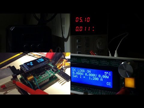
Youtube video of me testing the addon board installed on the C64 Saver 2. Note that it is not necessary to have an addon board for the C64 Saver 2 to work, however some pins need to be shorted for the C64 Saver 2 to work standalone.
The old design
I have decided to release my older C64 Saver v1. The board that fits inside a connector. Time and skill is super high on this product so be warned ! (SMD 0603, solder blob connections, tight spaces and short circuit hazards).
Gerbers
If you are looking for gerbers, click the releases tab. There you will find a zip file of gerber for each release.
Changelog:
Addon Board 1.3 (2019-05-24)
- Changed optocoupler footprint to more common SOIC-4_4.55x2.6mm_P1.27mm
- Larger 5V regulator on 9vac side for less heat
- replaced 100uF tantalum with 3x 47uF 1206 MLCC
- kicad 5.1.0 project
Addon Board 1.2 (2018-11-11)
- Swapped HOLD_ with SENSE_VAC on the MCU. SENSE_VAC needs ADC.
- Correct the mixed up SDA and SCL.
- 5V supply to the 5V section is moved to VIN+ (before the shunt). To not pull power through the sensing resistor.
- 4k7 I2C pullups.
- C64 Saver 2.4 (2018-09-23)
- Support lower Vth on Q1. Resistor divider R7 and R8.
- Remove C1 to make room for resistor divider.
- Changed R5 to 3k3 to reduce BOM size.
- New layout and routing.
Addon Board 1.1 (2018-09-23)
- ATtiny85 is a 8S2 package and two mm wider than SOIC8.
- Read overvoltage signal on reset pin using ADC. Added voltage divider.
- Replace MCP1700 with MCP1703. Supporting higher Vin_max
C64 Saver 2.3 (2018-08-18)
- Q1 2N7002 pin 1 and 2 rotated
- Q2 Reversed drain and source
- Increased pullup on Q1 drain.
- Repurposed R5 as pullup for Q1 drain.
- tested bodged v2.2 prototype, working!
C64 Saver 2.2 (2018-08-16)
- R1 was rotated.
C64 Saver 2.1 & Addon 1.0 (2018-07-23)
- 5x 9VAC pins. 9VAC1 current (4x) + 9VAC2.
- Moved GND pin.
- Changed board size to fit Hammond1551g
- C64 Saver board:
- Smaller throughole resistors
- Moved C1 closer to input circuits.
- Addon board:
- VAC sense circuit with voltage divider.
- 5V regulator on VCC pin. RAW pin disconnected.
- Pullups on I2C busses.
- SSOP-4 optocoupler packages
- Another regulator on the 5V side to protect the iso1541 and ina219.
C64 Saver 2.0beta & Addon 1.0beta (2018-07-02)
- New design.
- Protected sensitive parts.
- baseboard: throughhole parts.
- C64 saver 2 addon board.
- problem: has conflicting pinouts.