Files
| Files | |
|---|---|
| Resources | |
| .gitattributes | |
| .gitignore | |
| A-BRIDGE.brd | |
| A-BRIDGE.sch | |
| README.md | |
| eagle.epf |
README.mdView this project on CADLAB.io.

A-BRIDGE

Source files for the A-BRIDGE motor driver board

The A-Bridge is a small dual H-BRIDGE based on the integrated DMOS full-bridge A4950, capable to run 2 motors with a continuos current of 3A (3.5 with a heat dissipator) and a peak current of 5A. The bridge operates in PWM LAP, so, compared to the typical PWM SM control, you have less resolution but a more precise control of the speed. The inverted PWM signal required for LAP control is generated internally with a 74HC240 tri-state inverter, that also gives you the possibility to disable the bridge and the motor using the Enable input.

FEATURES:
 + Control 2 brushed DC motors
 + Input voltage: 8-40V
 + Output current: 3A continuos, 3.5 with heat dissipator, 5A peak
 + Overcurrent  short circuit protection
 + Enable input to disable the bridge

WARNING:
Some motor manifacturers (e.g. micromotors) use capacitors to reduce spikes and noise, it's recommended not to use that type of motors with this bridge. Check the motor's specification to know if your motor has the capacitors.

How to use

Basically this is a H Bridge, the only difference between this and the other typical commercial bridges is the integrated LAP control, this mean that you can control both speed and direction using the same signal. In particular:
| PWM duty cycle | Motor speed |
|---|---|
| 0% | Full Backwards |
| 50% | Brake |
| 100% | Full Forwards |
The ENABLE pin is used to disable the bridge. When LOW the bridge is operating at normal condition, when HIGH the bridge will enter in low power standby mode after 1ms. This is useful because the brake condition, with duty cycle 50%, does not means that the motor is turned off, but means that the motor is braked, and it will draw current to remain still. This is the worst efficience condition for the bridge, then, unless with small motor, it will heat up very fast. I recommend you not to remain in brake conditon for more than a half a minute. Therefore, for simply stop the motor you can set duty cicle to 50% and then disable the bridge with EN pin.
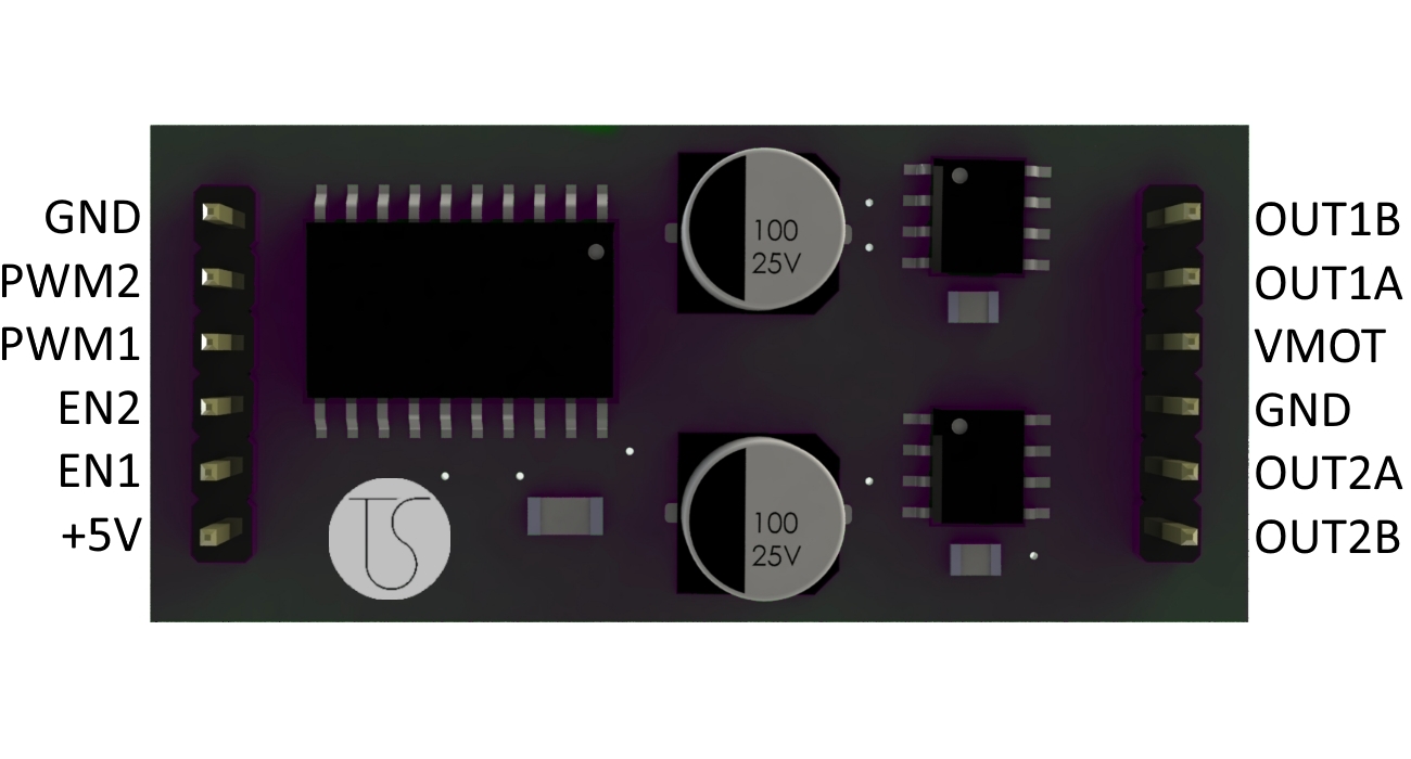
The circuit is very simple, basically it consist of two A4950, the 74HC240 and 5 bulk capacitors.
The A4950 can also provide a current feedback, but the sensing resistor also triggers the automatic current limiting system of the IC, that decrease the maximum output current. For example, a 0.25ohm resistor would limit the maximum current to 2A. This is the reason why i choose not to use the current sensing in this version of the board. If you want the current sensing feature you can use a external ammeter IC or consider the powerful uBridge by Officine Robotiche.


TESTING
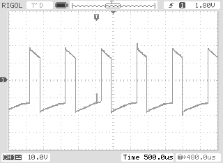
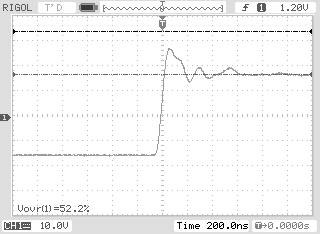
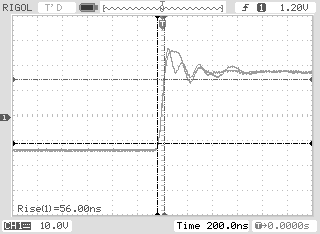
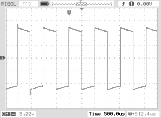
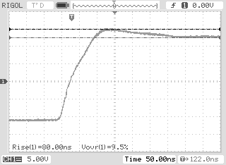
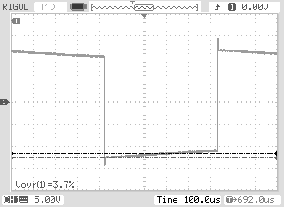
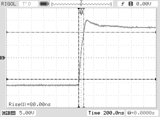
Every bridge is tested with various conditions of load. The tests measures voltage drop, voltage overshoot, rise time and temperature. Here you can see differents measures obtained with 2 different motors: a micromotors 12V 300mA geared motor and a lawnmower motor, running at 20V and absorbing 600mA with no load. You can see that with the lawnmower robot motor the voltage overshoot is really high, this happens mainly because the Arduino (which i used in this tests) produces the PWM signal with a too low frequency, 1Khz or 5Khz depending by the pin. To use big motors i recommend to use a frequency PWM at least of 10-15Khz, for example by using the setPwmFrequency function on Arduino or by using another microcontroller (e.g. ARM or PIC)
Micromotors motor:
Lawnmower motror:
