


Files
There are no circuits or boards in this repository.
| Files | |
|---|---|
| documentation | |
| hardware | |
| software | |
| LICENSE | |
| README.md |
README.mdView this project on CADLAB.io.
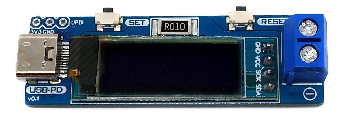
USB PD Adapter
The USB PD Adapter is a USB Power Delivery trigger and monitoring board that enables you to use almost any USB Type-C PD power supply to run your projects with different selectable voltages and high currents. Important values such as voltage, current, power and energy are displayed on the OLED. The USB PD Adapter is based on the cheap and easy-to-use CH224K multi fast charging protocol power receiving chip, the INA219 voltage and current sensor IC, and an ATtiny204, 214, 404, 414, 804, 814, 1604 or 1614 microcontroller.
- Design Files (EasyEDA): https://oshwlab.com/wagiminator/attiny814-usb-pd-adapter
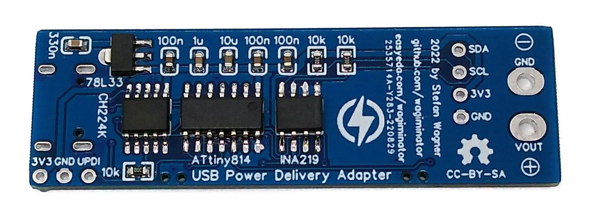
Hardware
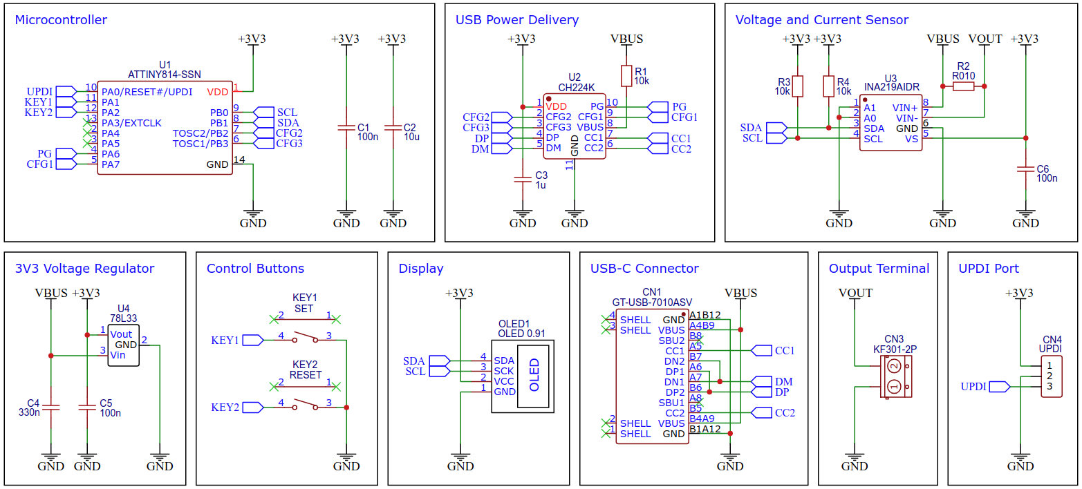
Schematic
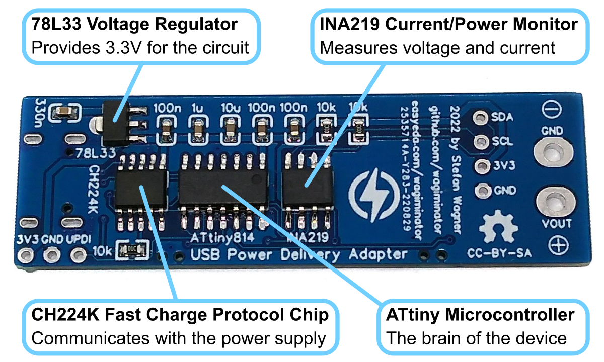
78L33 Voltage Regulator
The 78L33 is a simple and inexpensive voltage regulator that can convert input voltages up to 30V to an output voltage of 3.3V with an output current of up to 200mA and a dropout voltage of 1.7V. The 78L33 supplies all elements of the circuit with 3.3V.
CH224K USB PD Power Receiving Chip
The CH224K is a USB PD power receiving protocol chip, which integrates PD3.0/2.0, BC1.2 and other fast charging protocols, automatically detects VCONN and analog E-Mark chips, supports up to 100W power, and has built-in PD communication module. It also integrates output voltage detection internally to support overheating and overvoltage protection. It features:
- 4V to 22V input voltage
- PD3.0/2.0, BC1.2, QC3.0/2.0, AFC and other fast charging protocols
- USB Type-C PD, positive and negative insertion detection and automatic switching
- E-Mark simulation, automatically detects VCONN, supports 100W power PD request
- requested voltage can be dynamically adjusted through a variety of methods
- high integration of single chip, simplified peripheral and low cost
- built-in over-voltage and over-temperature protection module
The output voltage is selected via three configuration pins of the CH224K, which are connected directly to the ATtiny and is set according to the following table:
| Output Voltage | CFG1 | CFG2 | CFG3 |
|---|---|---|---|
| 5V | 1 | - | - |
| 9V | 0 | 0 | 0 |
| 12V | 0 | 0 | 1 |
| 15V | 0 | 1 | 1 |
| 20V | 0 | 1 | 0 |
The CH224K's PG pin is open-drain, pulling the input to ground when the requested voltage has been successfully negotiated with the USB PD power supply. It can be used to drive an indicator LED or a high-side P-channel MOSFET for power path control. Here this pin is connected directly to the ATtiny, which can query the status with the help of an internal pull-up resistor.
INA219 Current/Power Monitor
The INA219 is a current shunt and power monitor with an I²C-compatible interface. The device monitors both shunt voltage drop and bus supply voltage, with programmable conversion times and filtering. A programmable calibration value, combined with an internal multiplier, enables direct readouts of current in amperes. The selected shunt resistance of 10mΩ enables both a very small influence on the circuit and a measurement with a resolution of 1mA. For an accurate measurement, a shunt resistor with a low tolerance (1% or better) should be selected. The INA219 is used here to measure the output voltage and output current. It communicates with the ATtiny via I²C.
ATtiny Microcontroller
The ATtiny microcontroller handles the user interface, the control of the CH224K and INA219, and the calculation and display of the measured values. The user interface utilizes two buttons and an SSD1306 128x32 pixels OLED display. In this application, the ATtiny runs at only 1MHz to keep power consumption low and thus avoid overheating of the 78L33 voltage regulator, especially at 20V output voltage.
The following microcontrollers can be used: ATtiny204, 214, 404, 414, 804, 814, 1604 or 1614. However, since the firmware in the current version already requires almost 2KB of flash (depending on the compiler settings), the use of an ATtiny202 or ATtiny212 is not recommended, since there are hardly any reserves left for future upgrades.
Compiling and Uploading the Firmware
If using the Arduino IDE
- Open your Arduino IDE.
- Make sure you have installed megaTinyCore.
- Go to Tools -> Board -> megaTinyCore and select ATtiny1614/1604/814/804/414/404/214/204.
- Go to Tools and choose the following board options:
- Chip: choose the chip you have installed
- Clock: 1 MHz internal
- Leave the rest at the default settings.
- Connect your programmer to your PC and to the UPDI header on the board. Make sure the programmer works with 3.3V.
- Go to Tools -> Programmer and select your UPDI programmer.
- Go to Tools -> Burn Bootloader to burn the fuses.
- Open the sketch and click Upload.
If using the makefile (Linux/Mac)
- Connect your programmer to your PC and to the UPDI header on the board. Make sure the programmer works with 3.3V.
- Make sure you have installed the latest avr-gcc toolchain.
- Open a terminal.
- Navigate to the folder with the makefile and the sketch.
- Run
DEVICE=attiny814 PROGRMR=serialupdi PORT=/dev/ttyUSB0 make installto compile, burn the fuses and upload the firmware (change DEVICE, PROGRMR and PORT accordingly).
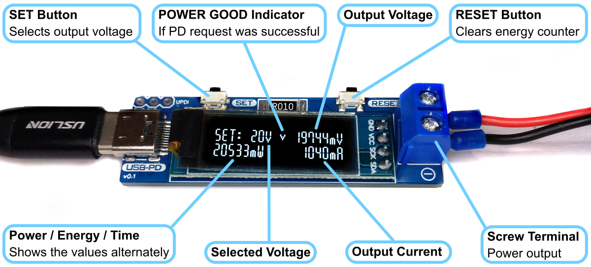
Operating Instructions
- Connect the USB PD Adapter to a USB Type-C PD power supply using a USB-C cable.
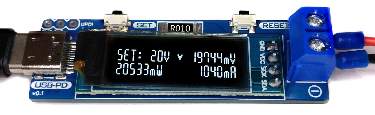
- Use the SET button to select the desired output voltage. An hourglass appears on the display while the device is communicating with the power supply. If the negotiation was successful, a tick is displayed and the desired voltage is present at the output.
- Connect the device to the power consumer via the output screw terminal.
- Use the RESET button to clear the energy counter.
References, Links and Notes
- 78L33 Datasheet
- CH224K Datasheet
- INA219 Datasheet
- ATtiny814 Datasheet
- SSD1306 Datasheet
- CH224K USB PD Decoy
- IP6520 USB PD Source
- ATtiny412 USB PD Inverter
- TI Primer on USB PD
- 128x32 OLED on Aliexpress
License

This work is licensed under Creative Commons Attribution-ShareAlike 3.0 Unported License. (http://creativecommons.org/licenses/by-sa/3.0/)