Files
README.mdView this project on CADLAB.io.

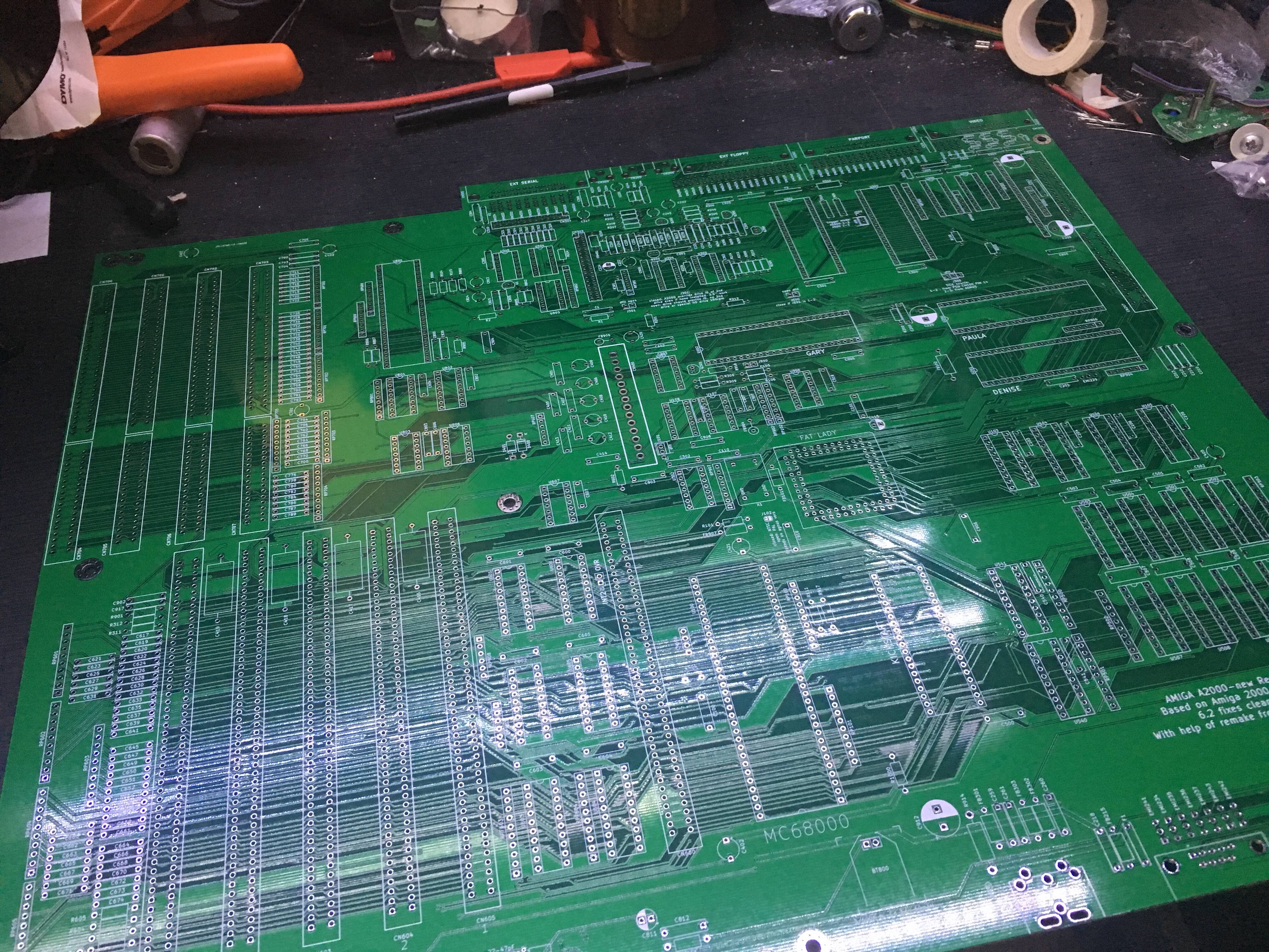
Amiga 2000 KiCAD Schematics and PCB

Revision

Current schematics are based on 6.0 plus known 6.2 fixes.

Deviations from the original 6.2:
- The snapped resistor net around the 68k have been removed from schematics.
- The two res net soldered to U603 and U604 have a dedicated footprint on PCB
- The bridge C1/R1 also has footprint, same for R2 from U800
- The PST reset have dedicated footprint, diode have been removed
- There is an aditionnal header, J3, with OVR and INT2 breakout for accelerator cards, easier than clipping on chips
- Jumpers should have a default working configuration labelled on the PCB plus various notes
- The keyboard connector footprint have been modified to handle either the original one, or a standard MIDI one
- The battery terminals are just a two pins header, just plug some wires and use any battery you want aside or glued or whatever

TODO
- Check if there is no useless local labels that could have generated spurious nets connected in the PCB
Notes
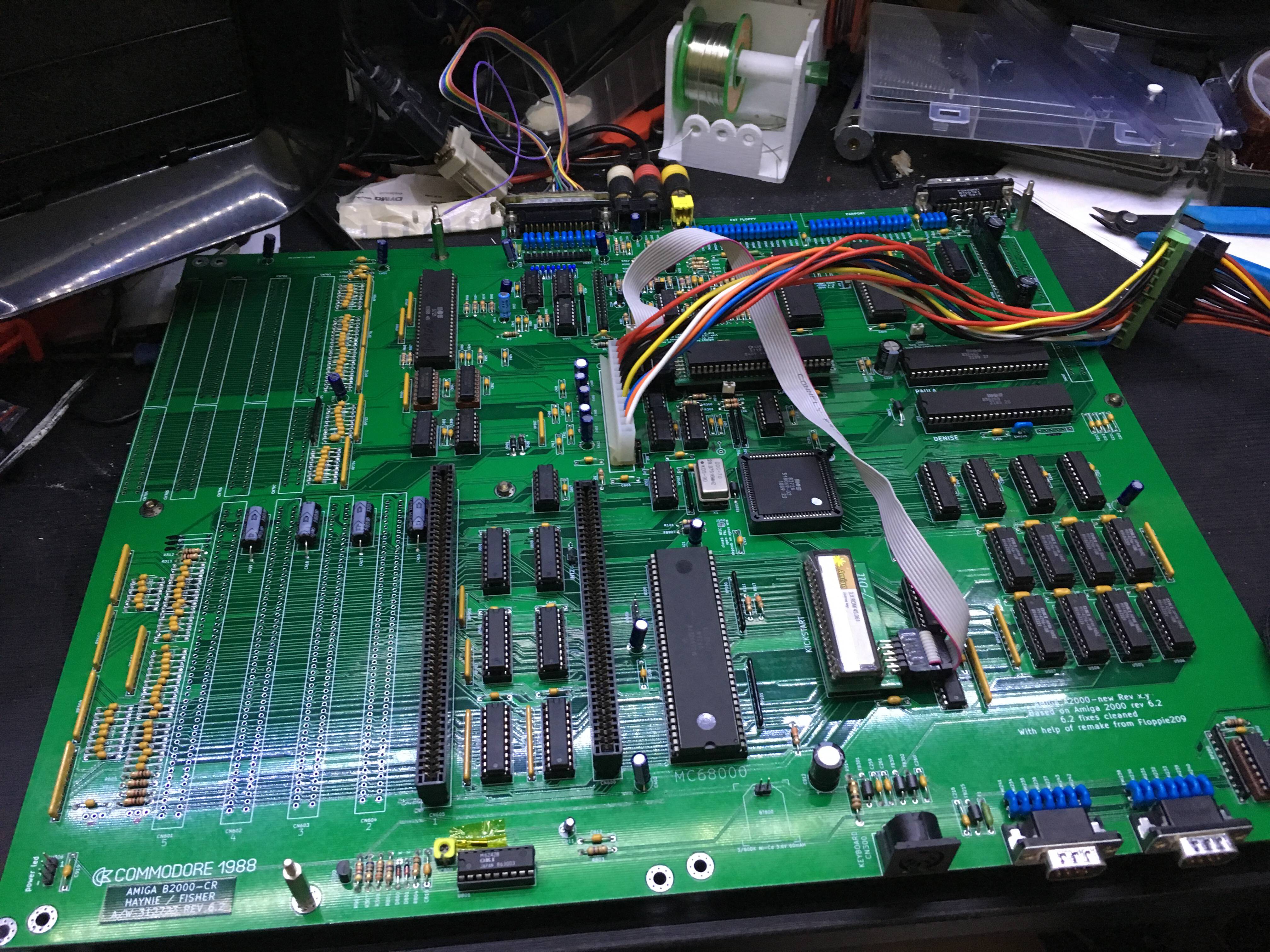
The capacitors on the left of the POWER Connector are somewhat troubling if you don't have a lot of experience.
So the five caps should be placed like this (IGNORE the + footprint on the PCB):
- C400, GND pin on left
- C406, GND pin on left
- C408, GND pin on right
- C410, GND pin on left
- C412, GND pin on right
If using an A500-Flash from Retro 7-bit, U540 and U203 can't be socketted or they will be too high.
Building
The file amiga2000.csv contains a full Mouser BOM, around ~150€.
Memory and RTC chip should be got from eBay, same for the PST reset thingy (U1).
The ISA (8bit and 16bit connectors) fits perfectly a full-length connector got from like an old PC motherboard.
The the table at the bottom of this README for a list of DigiKey and Mouser P/N for ZORRO, CoPro, Video and ISA slots.
Other chips (paula, denise, CIA, etc.) are got from a donor motherboard.
If building it for real: first test the PCB for short between GND and the various power lines (+5V, -5V, +12V, +5V_USER, etc.), the zorro should have all.
Then solder all the electrolytics caps, connect power, re-test all the lines.
Solder everything else, don't populate ICs yet, re-power and re-test.
Then you can add ICs and run DiagROM and then enjoy.
DO NOT POPULATE: J1, J2, C902, C917, R901, FB904, FB906, RP904, RP906, RP905, C230, C240, they are unpopulated on factory 6.2 rev, so, let them as-is.
Testing
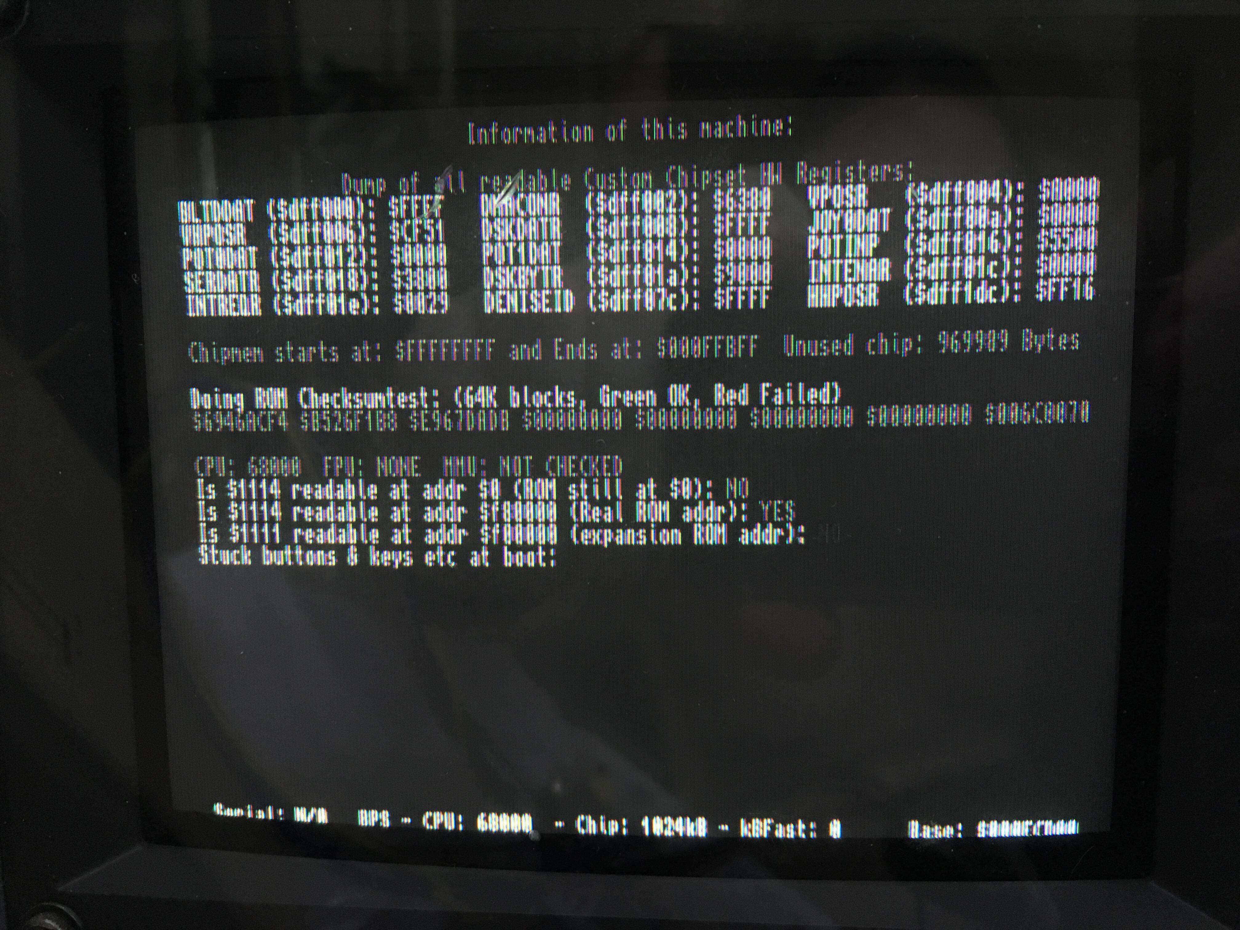
My first prototype have been tested with DiagROM v1.1.
Working: mouse, zorro listing of detected cards, composite video out, video out, serial (out at least), one audio ch (the other one should work too), keyboard. Booting a workbench from the accelerator CF sorta work until noise issue or something make any disk I/O hang and crash.
Left to test: floppy, parallel port, if the RTC works properly.
The DiagROM detects 1024kB of chipmem, the extended test goes all the way up to 1023kB and then throw an error, I'm not sure if it's a DiagROM issue or just expected.
Libraries
Uses libraries from https://dev.sigpipe.me/dashieelectronics/kicad_libraries
Various tools
extract_labels.py
Use this script to quickly extract all Global Labels from wanted sheets.
./extract_labels.py agnus.sch amiga2000.sch chipram.sch coprocessor\ slot.sch denise.sch expansion\ logic.sch parallel.sch paula.sch pc\ slots.sch power.sch processor.sch serial.sch zorro.sch
License
CC0
Sources
My own dying 6.2 A2000 board.
This pre-6.2 schematics, best scan quality available...: - http://amiga.serveftp.net/Schematics/A2000_schematics/A2000_rev6_schemat...
A big thanks for Floppie209 for his 1:1 board replica: - https://github.com/Floppie209/Amiga2000-remake/
Whithout Floppie work I wouldn't have had enough motivation to sacrifice a sorta working board for measurements.
Documented 6.2 fixes: https://wiki.sigpipe.me/amiga:a2000:rev6.2fixes
Random parts numbers
| for | Digikey PN | Mouser PN | Manufacturer PN | EOL |
|---|---|---|---|---|
| Zorro (100pins) | A121376-ND | 571-5645235-3 | 5645235-3 | no |
| CoPro (86pins) | A144213-ND | 571-1-5530843-0 | 1-5530843-0 | no |
| Video Slots and ISA16bit (36p) | A31716-ND | 571-5530843-3 | 5530843-3 | no |
| ISA 8bit (62) | A121053-ND | 571-7-5530843-0 | 7-5530843-0 | no |
| Full lenght ISA slots | A101941-ND | 571-5176139-2 | 5176139-2 | no |
| Power connector, 14 pins | 538-26-60-4140 | 26-60-4140 | no |
Pictures


